Being able to modify the user coordinate system (UCS) in AutoCAD is the first step to being able to draw more complex 3d objects. This is done by using the UCS command.
Watch the video below or on YouTube to see how this command can help you with your 3d drawing or follow the instructions below that.
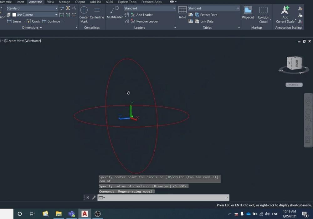
How to Modify the UCS (User Coordinate System) in AutoCAD
Total Time: 1 minute
-
Check current UCS/WCS state
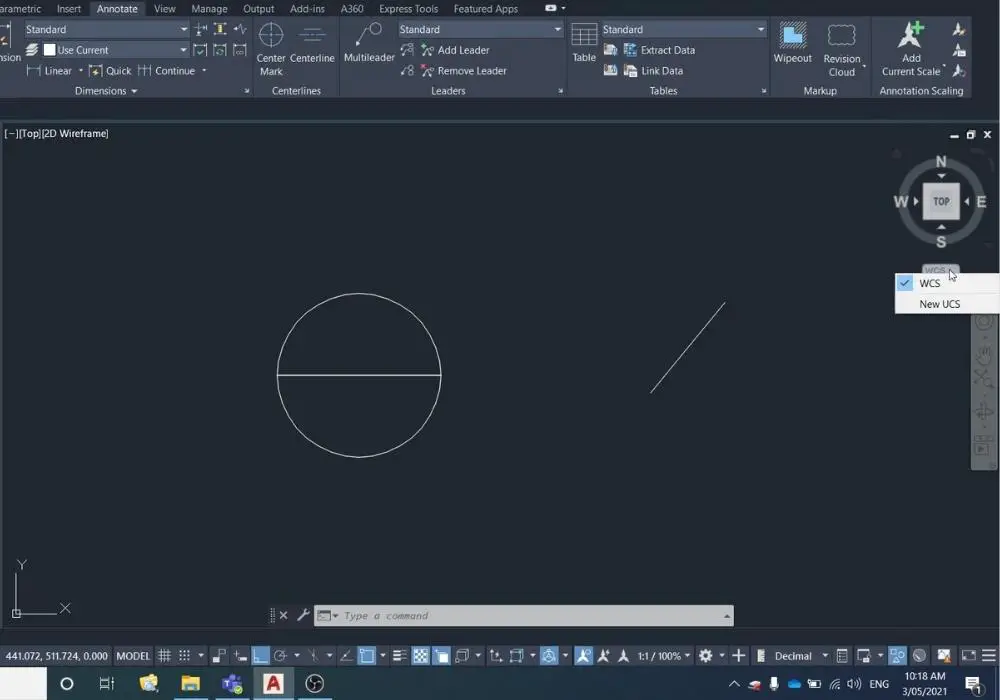
Under the ViewCube check that it is showing WCS, and if it isn’t then select WCS from the dropdown list.
If you can’t see your ViewCube, read my blog here about recovering the ViewCube.
-
Draw circle in XY plane
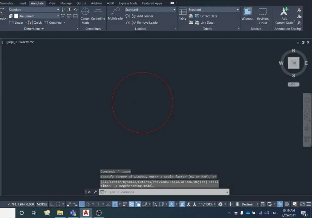
Using the circle command CIRCLE (shortcut = C) select anywhere and anysize to draw a circle.
-
Orbit model space
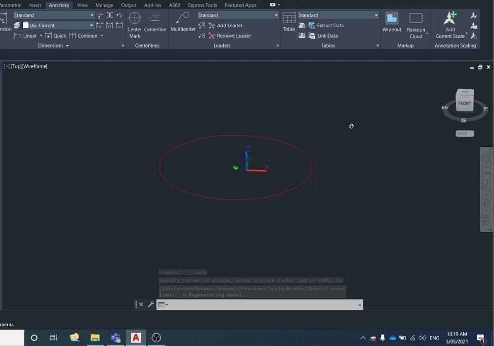
Holding Ctrl and pressing the middle button on your mouse rotate the view around so you are looking at the front of the ViewCube.
-
Select view from ViewCube
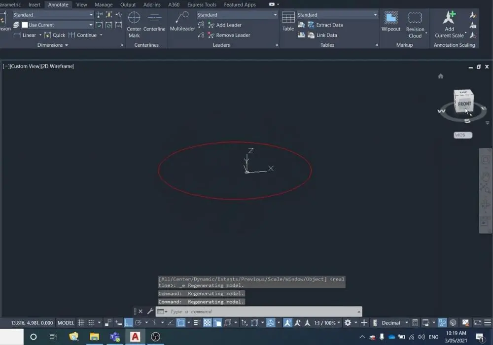
When you can see the front of the ViewCube click it and the model space will snap to that view.
-
Draw circle in XZ plane
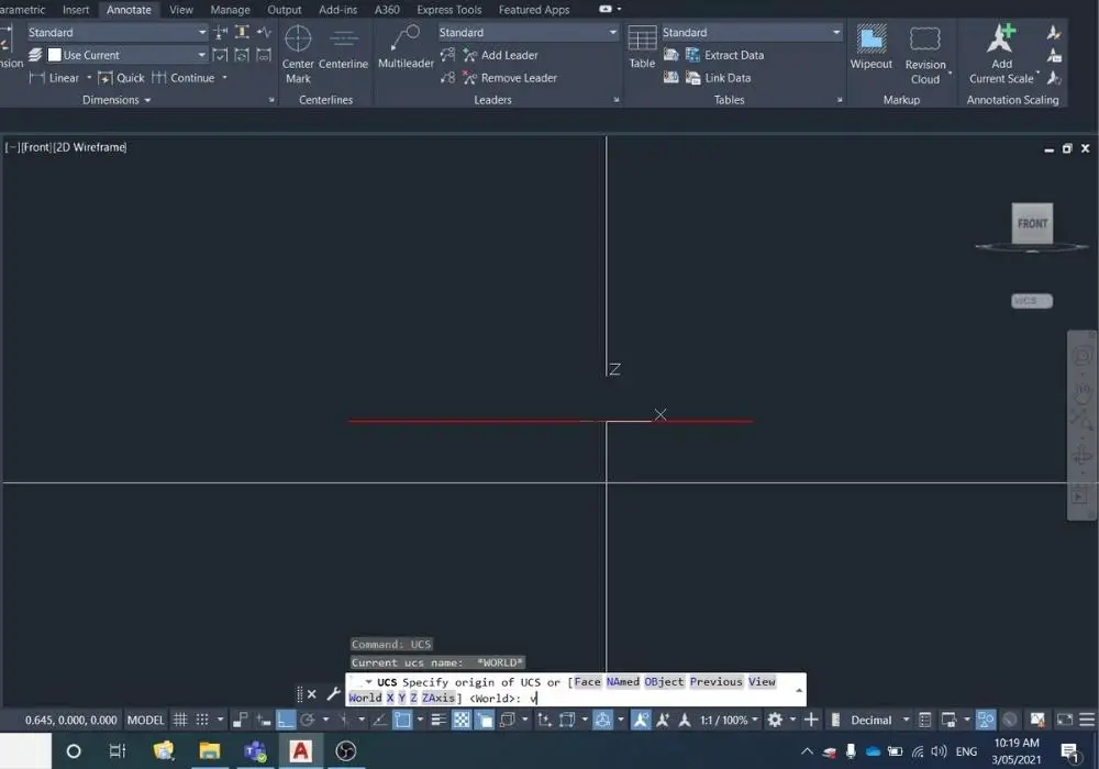
To be able to easily draw an intersecting circle in the XZ plane, type in UCS into the command bar, and select or type in VIEW.
This will change the UCS to match your current view.
-
Draw second circle
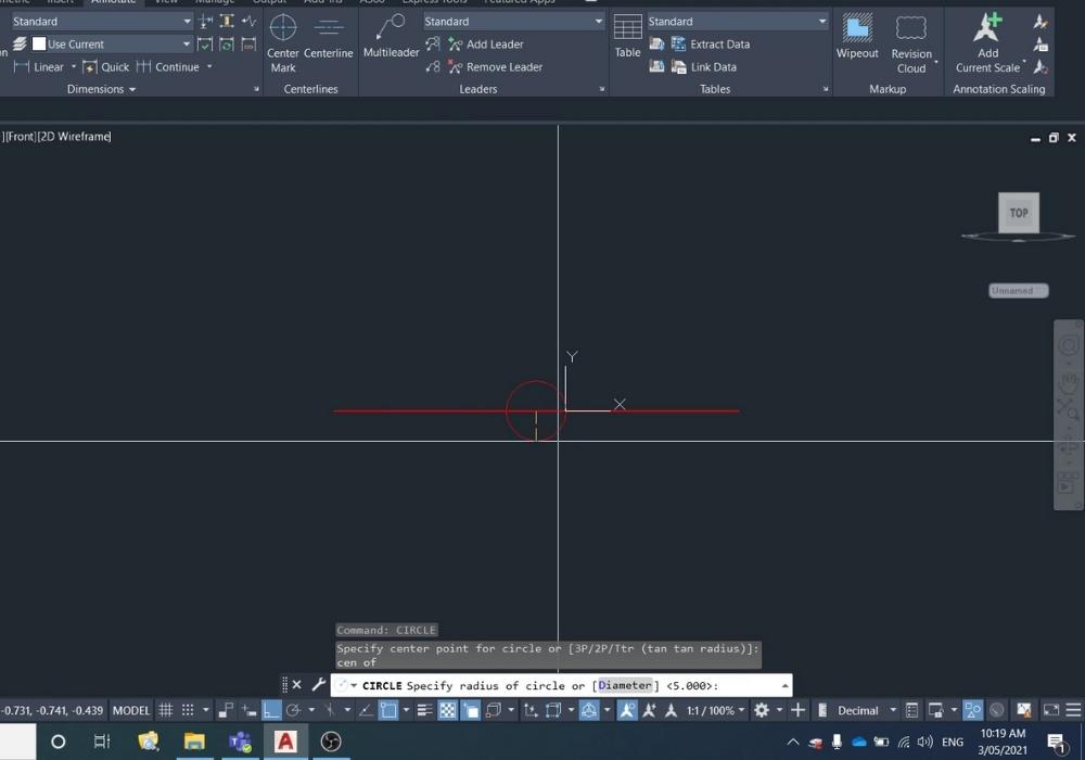
You can now start the CIRCLE command and snap to the centre of the existing circle, and draw it at the same radius.
-
Inspect results

You can now view your results by orbiting the model space by holding Ctrl + middle mouse button and rotating around the model space.
-
Reset ViewCube to WCS
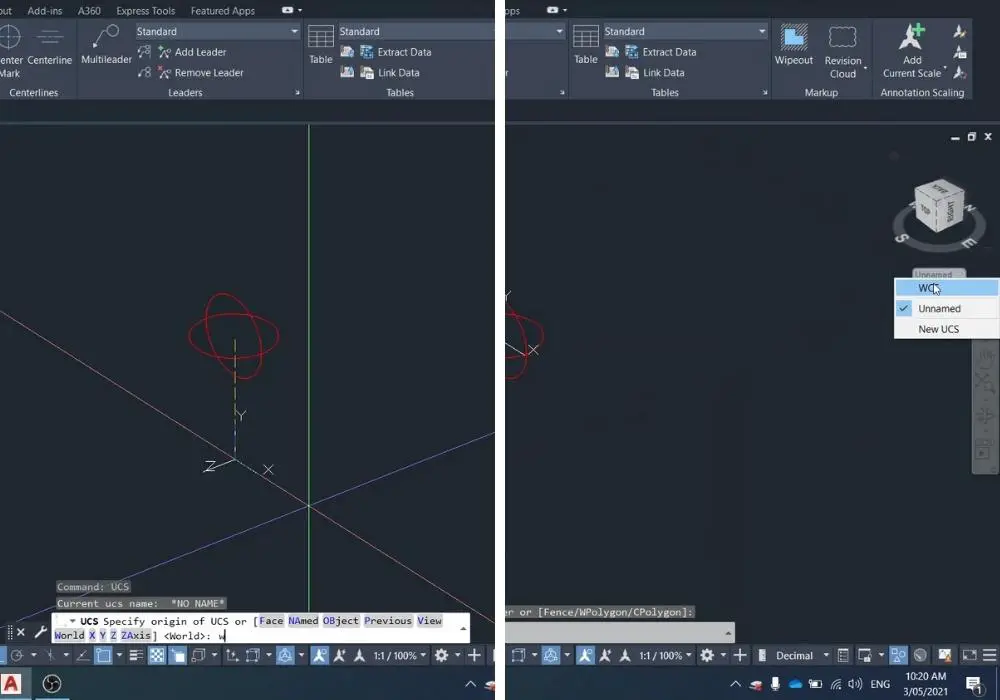
Once you have finished working in your custom UCS, you can reset the model space/ViewCube one of two ways:
(1) Type in UCS into the command bar, then type in WORLD to reset to WCS (world coordinate system)
(2) Underneath the ViewCube select the dropdown list and select WCS from the list. -
Example 2 – Non square UCS
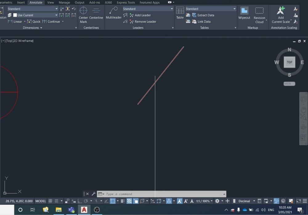
To create a UCS that isn’t square to the ViewCube (i.e. you can’t just press different faces of the view cube), what I do is draw my own axis by copying the feature I want my UCS to be aligned with and rotating it 90 degrees.
-
Draw axis
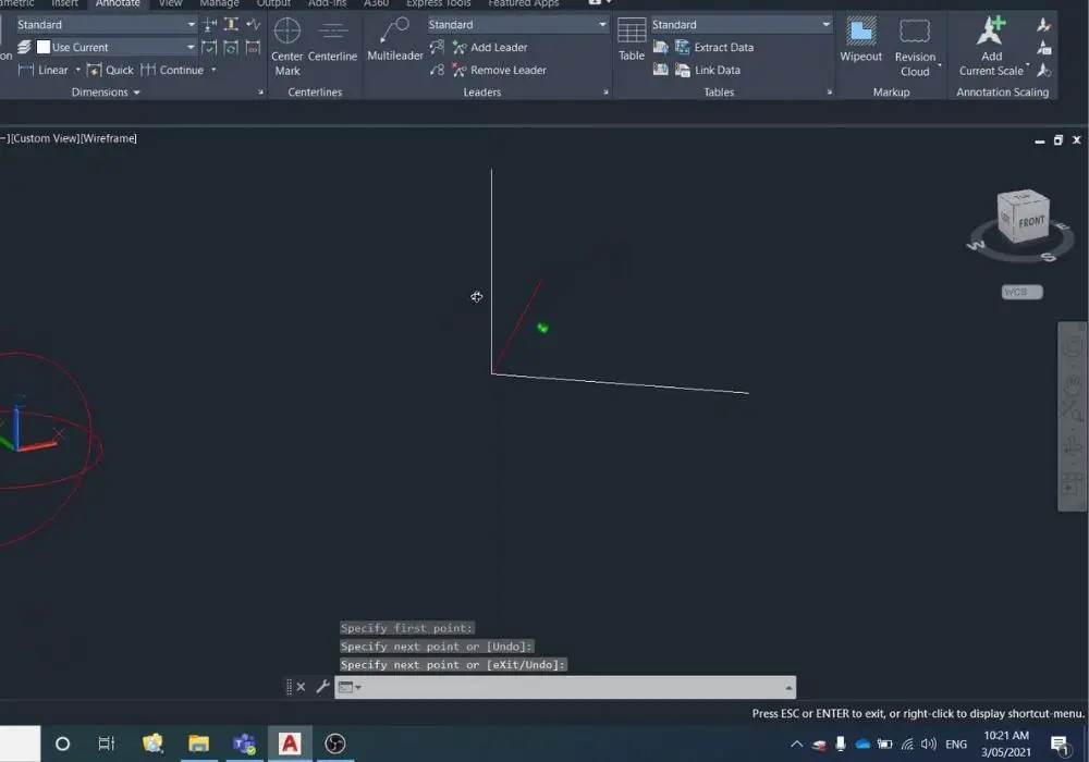
Drawing the axis is a pretty manual step. You can do this using the line and copy and rotate commands.
-
Create custom UCS
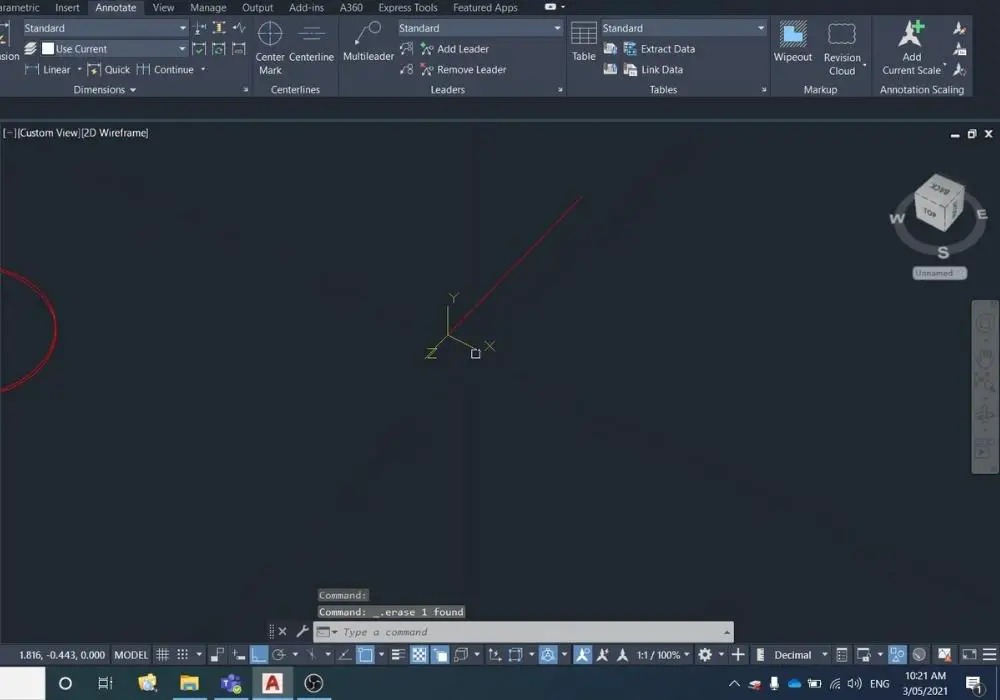
Type in UCS into the command line and then just follow the prompts:
(1) Select an origin point
(2) Select the direction of the X-axis
(3) Select the direction of the Y-axis
(4) Select the direction of the Z-axisYou can see the resulting axis as it appears in the above image at the end of the line.
If this step is confusing watch my video starting from here.
Final Thoughts
I hope this video was useful to you.
Being able to modify the UCS is a basic step to being able to draw more complex 3d shapes and objects.
FAQs
How can I get my UCS back to normal?
You can either:
(1) Type in UCS into the command bar, then type in WORLD to reset to WCS (world coordinate system)
(2) Underneath the ViewCube select the dropdown list and select WCS from the list.
How do I reset my UCS?
You can either:
(1) Type in UCS into the command bar, then type in WORLD to reset to WCS (world coordinate system)
(2) Underneath the ViewCube select the dropdown list and select WCS from the list.
How do I rotate the model space view to match the viewcube?
You can press the faces on the ViewCube to modify and change your view of the model space.
